CHAPTER 1
In this chapter I will be discussing about the main functions of SON, its components, elements and how does it atomizes the whole LTE network infrastructure. I have organised this chapter in the following way and will explain each of the component respectively.
- OAM
- Automatic Configuration Features
- Neighbour Relation
- Automatic Neighbour Relation management
- Connectivity Management
- Self Test
- Automatic Inventory
So, lets get started with the detain explanation, description and working of the OAM system first.
1–OAM (Operation, Administration and Management)
1.1Introduction
OAM stands for Operation, Administration and Management systems. As we have discussed in the earlier chapters that most of the network operations today is controlled and managed by a central entity which is known as the OAM system. Mainly in a centralized system architecture all the Self-Configuration, Self-Optimization and Self-Healing operations are controlled through the OAM system. In the next paragraph a brief description of what functions does the Operation, Administration and Management system take care of is explained.
Get Help With Your Essay
If you need assistance with writing your essay, our professional essay writing service is here to help!
Operations system deals in both the administration and management systems. It is basically a centralized control structure which keeps coordination between both the other systems. Administration system as it stands control all the administrative tasks like networks design, assignment of addresses, keeping network up to date and other administrative functions. And lastly the Maintenance system maintains and keeps the network running through keeping check of all the elements, executing appropriate diagnostic functions, monitoring network and resetting the components or whole network if required. All these components work parallel to keep the network in operational state.
1.2Architecture
For any network to operate optimally it is very necessary to keep check on all the elements. The operator of network should have a system through which he can make sure that there is no fault and network is running normally. In the figure 1.1 below a high level OAM architecture architecture is represented.
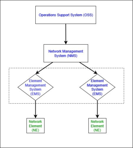
OAM Architecture Fig1.1
As it is clear through fig 1.1 that OAM has further devided management layers and provided dedicated servers to each management layer to deal with its functions. All the management servers serves their corresponding nodes layer by layer to perform the management tasks. Network protocols has been defined at each interface onto the Network Element or end user for execution of effortless management functions.
Though the architecture diagram we can conclude two main logical functions that devides the OAM according to their functions and roles. These functions are given below,
- Network Management function
- Element Management function
Mainly in the network managements systems, OAM is addressed as the entity which controls, maintains and configures the network. The term OAM is used in the 3GPP documentation for the network management functions. As five main sub-functions of Network Management Systems are derived from the main functions of OAM and hence NMS is also reffered as the OAM systems in many contexts. OAM when demand lot of provisonal functions then it is known as the OAM&P, P stands for provision in this situation. The functional elements of Network Management System is given in the figure 1.2 below.
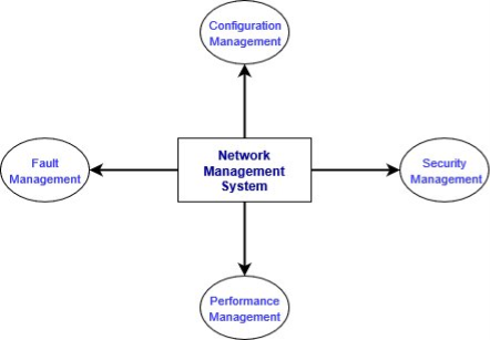
Fig 1.2
In the next part I will be discussing two very important management functions related to the OAM architecture and those are as follows,
1.3Element Management System (EMS)
As we know network element is an entity composed of the physical hardware. Processes and executions are performed on those physical devices to provide service the users. Therefore, a management technique to manage these elements of the network is known as the Element Management System. The management system a very broad topic but I will keep focus on the main components which integrates with the SON technique for the optimization of cellular networks. As we can see in the fig 1.1 the Network management system collects all the data from EMS and EMS gathers all useful measurements for the NE respectively. The difference is NMS mainly execute the aggregated measurements from NEs to accomplish required functions but EMS works on individual NE at a time. Below is the high-level architecture of the EMS and the components it interacts with.
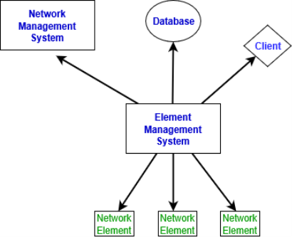
Fig 1.2
Furthermore, I would give a brief description of the components shown in the fig 1.2 above. The EMS connects to the NMS server to provide all the collected and aggregated information or measurement from the network elements. NMS makes decisions based on these collected data from EMS. The client is used to show or present the data to user with a user friendly graphic user interface. The operator can login through the client to configure and maintain network when needed. The database function is to store all the usable measurements and information. These measurements are used when a fault occurs in the Network Element. Evaluating and comparing the network performances with these measurements give a complete sight of what might be causing the errors in the network. And the last component which is the Network Element is same we have discussed earlier, a physical device used to execute all the processes and functions.
A question that arises here is that the network elements can be managed and configured through accessing the devices itself so why do we need a central Element Management System? Therefore, the need of this management function is explained as follows.
1.3.1Requirement of EMS
Network are getting very complex as new functionalities and services are added very frequently. And with that, new vendors and service providers are introducing themselves in market. As the network size is enhancing the operations at the network element end is also increasing. This operation management demands high cost and effort. Therefore, to minimize the cost, effort and a centralized solution to manage the networks were provided by the 3GPP. An appropriate and user-friendly interface is very vital to perform and manage managerial tasks with ease. Some main issues which the operators of telecom companies were facing are described in the next paragraph.
Firstly, Due to the development of fresh network elements and services there was a need to provision diverse elements from different vendors. For example, even in a single network GSM, UMTS and LTE can work side by side therefore a management system was required which can gather all the data from all the network elements. Secondly, the complexity issues were raising as of now many multiple functionalities are merging into one single functionality which makes the network complex. And lastly but the most important is the cost. The cost associated in dealing with each element individually was very high, therefore to manage complete network and its services remotely and through a central entity which has all the data and measurements from all the network elements can reduce huge costs.
Progressing through EMS now I will explain the functions and services EMS provides to the network and how it interacts with its upper layer that is the Network Management System.
1.3.2Functions of EMS
Element Management System basically manages the base stations that is eNodeBs in the LTE network architecture in accordance with SON. The main functions which EMS features while managing the network elements are given below.
1.3.2.1Provisioning and Installation of NE
When a base station that is eNodeB is connected to a power station but not yet configured and basic setup is not initiated, eNodeBs at this point needs to connect to the network to perform basic functions. So, the Self-Configuration function of SON is initiated to make a connection, eNodeB for connectivity requires an IP-address and OAM support to start functionating. For obtaining basic configuration and parameter settings the eNodeB connects to the OAM system.
Find Out How UKEssays.com Can Help You!
Our academic experts are ready and waiting to assist with any writing project you may have. From simple essay plans, through to full dissertations, you can guarantee we have a service perfectly matched to your needs.
View our academic writing services
Now the EMS element in the OAM must provision, support and provide these basic configuration settings to the eNodeB. The EMS checks is they can provide the service base station is asking for. The inventory management server is checked for this purpose. Once the resources are available and identified the configurations are uploaded onto the base stations and correct parameters are set up. At this point the network elements are ready to be interconnected with the network and start functioning. This technique is used in the Self-Configuration function of SON for the basic connectivity with the network. Furthermore, this function of EMS also maintains the backup and restore points for the network element. Downloading, installing the patches and newly updated software on the eNodeBs are handled by the EM system too.
The inventory system database in the EM system contains all the required parameter settings used by the eNodeBs for the self-configuration and auto-connectivity once powered on. Every element in the modern telecom services are automated through SON and a technician is only needed when something couldn’t be resolved automatically. At that point the engineer or operator just login through the EMS graphical user interface and handles all the faults and errors with ease.
1.3.2.2Managing User terminals and maintaining QOS
In a wide scale network, there are thousand of base stations and thousands of user-equipment are connected to these base stations. Therefore, to manage this big network is not easy at the operators end. The capital expenditure to deploy base stations and then the operational expenditure to maintain each single base station requires huge amount of cost and with cost excessive human effort is required to maintain base stations. Therefore, EM system manages these user terminals by gathering the statistics of all the users cell through cell and saves these measurements into the database. So, the message status between the base station and UE are attained in the shape of statistical reports. The vital data collected in these statistics are given below,
- All the successful calls.
- All the failed calls.
- Dropped calls.
- Successful HOs.
- Failed HOs.
- The traffic capacity that is throughput.
By gaining all these important statistics from the network the EM system analyzes and makes appropriate decisions when needed. Not only this but EMS uses these measurements to maintain the Quality of Service too.
1.3.2.3Network Support
Network support mainly aims in the activities related to the maintenance of the network. And as discussed earlier operators goal is to decrease the cost as much as they can. As much the network is well managed and well driven the cost will decrease. So, quality of management systems is inversely proportion to the cost. With the cost, there is one more concern that operators are facing and that is the lack of professional technicians. And both concerns can be mitigated through the automatic solutions. Therefore, automatic network systems reduce human intervention and cuts the cost too. And for the support of network automatically EMS functionalities are evolved. Main functionality that EMS provides for the network support are given below.
- Debugging and resolving software issues such as bugs and errors. EMS provides a method to automatically resolve these errors remotely.
- All the security statistics are handled by EMS which the network requires to handle and secure vital information and data.
- All the network faults and issues at the element level are mitigated through the EMS. As Network management system deals with the combined data and information from several network elements. But the EMS takes charge and record of each Element individually.
- And lastly EMS allows operators to login to the specific node for the purpose of upgradation or changing parameters. The operator does not have to go physically to the base station and login through its internal interface.
1.3.2.4Monitoring of Networks
The monitoring of networks is mainly done on the Network Management System but some of its function is executed on the EMS. EMS supports the NMS through some of its functionalities for the monitoring and control. First, we need to understand that monitoring of networks is executed on NMS and portions of these functions are performed on the EMS level. The EMS layer is below the NMS layer and therefore it provides major feeds to the layers above it. The monitoring systems main tasks which optimizes the network are given in the figure 1.3 below.
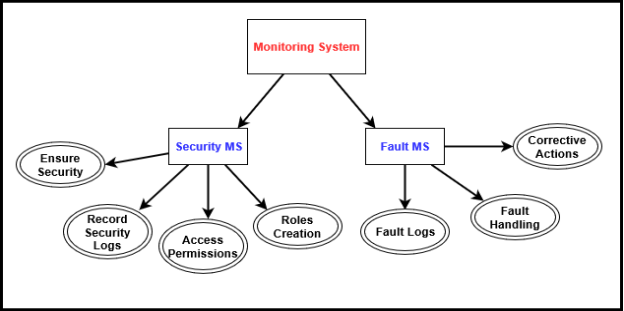
Fig 1.3
The 3GPP defines standards of OAM with very classified specification. And it is very clear that the OAM specification gives ease in implementing the management system for the network. There are other network management specifications like TMF but the 3GPP specification about the OAM is very broad and revolves around some specific function or technology. The specifications, standards, specifications and how does 3GPP uses SON to optimize networks are explained in the last chapter of this paper that is 3GPP specifications and its interaction with SON.
1.4Network Management System (NMS)
The network management system in the OAM architecture is capable of managing the complete network in a combined method that is, managing of radio transmissions, core networks and the base stations. NMS manages all these entities on one single platform. And due to the capability of managing everything on one single node the cost and human effort is decreased exponentially. There is a term used in the management system called FCPS which stands for Fault, Configuration, Performance and Security Management. And this function works on all the layers of the OAM model. On every layer, it has different function but the general explanation of FCPS is explained in the last portion of this topic. Basically, how NMS functions is explained in the example below,
Lets consider there is a fault detected on the NE. Because whenever an event occurs network element generates a log which notifies EMS of the event occurrence. EMS would collect these statistics from the NE. Now NMS responsibility is to tackle the issue and take corrective measures. To accomplish these goals NMS correlates the statistics from different NE and different events, this technique helps the NMS to discover the issue or fault by comparing different statistics. A real-time example of NMS working could be of a disconnection scenario between a base station and the media gateway. Logs and stats screening the connection lost will be generated on the elements of both base stations and the MGW. As base station and MGW are two different network elements and EMS always record the stats of specific network element individually. So, it might collect the stats from the base station or the MGW, but the Network Management System at this point records data from both the elements and then correlate them. Therefore, in the scenarios defined above the stats and logs from base station and MGW can be analyzed together which makes the work on NMS level easy to find the actual problem in the network. And when the problem is diagnosed NMS takes the proper corrective measure to mitigate the issue which EMS can not do by just gathering the logs of one network element. This is a case specific function of how NMS tackles the issues. The other functions and activities NMS performs to optimize the network are given in the next section.
1.4.1Activities performed by NMS
All the main activities that the NMS performs prior to any maintenance instructions or corrective measures are given below.
- Learn about all the elements available in the network. It works in two ways, manual discovery which is done by the operator and the second is automatic element discovery. In an auto discovery mode, this management system automatically discovers and identifies all the network elements and assign IPs to the particular element which requires it. The manual discovery is executed by the operator and manage the network elements that is assign IP addresses to the elements and discover all the elements in the network through the application menu.
- Gathering all the faulty data. The reason this activity is scheduled to be executed after the network elements discovery is to associate the faulty information with the specific element and components which are causing the error. In the NMS software, all the discovered elements form a tree type structure and hence associating the correct statistics with the corresponding element assists in debugging the fault.
- Collecting all the performance statistics and data. The faulty data discussed above is sent to the NMS only when they arise but on the other hand the performance logs and stats are stored in the files of network element itself. And these stats are downloaded on the NMS from the NE at the periodic intervals.
- User Authentications. All the internal user in the NMS needs to be authenticated for the security reasons. There are commands in NMS which can collapse the vital network components which can cause affect on whole network therefore, robust security needs to be implemented on the NMS.
- Collecting other configurations and data. The last activity executed by the NMS prior to start managing and maintenance of the networkall the other statistics and configurations in the element required in the NMS to execute any function is also collected from the NE.
So, when all the elements are discovered and prerequisite activities have been executed successfully the NMS is the all set for the management and maintenance tasks of the network. These functions, maintenance, corrective measures, fault detection etc. are performed by analyzing the earlier collected data from the NE. Main functions of the NMS includes outlining the flow of information, provisioning of network, troubleshooting, configured elements maintenance, making appropriate decisions for the optimal utilization of resources etc. The problem which sometimes arises is the parameter or configuration changes in the network elements. These changes must be updated on the NMS so that it can find an appropriate solution when required. Therefore, network elements are rediscovered at periodic intervals so that the most current statistics and data could be known to the EMS.
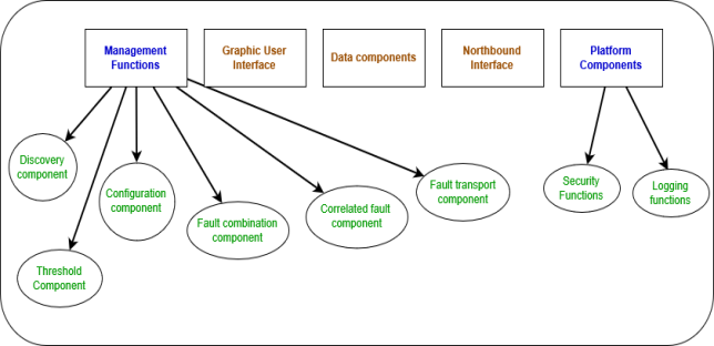
The next section would comprise of the NMS general architecture and the components which reside in the NMS. Description and explanation of these components are also given in the section below.
1.4.2NMS Architecture
Cite This Work
To export a reference to this article please select a referencing style below:


