CAD/CAM Analysis Post Module Assignment
Computer Aided Design (CAD) and Computer Aided Manufacturing (CAM) have become key tools to engineers responsible for designing new products in terms of their commercial appeal, look and feel, functionality, serviceability and disposal. Since 1998, a new field of engineering has been recognised as an academic discipline, that of Sports Engineering, which examines the interactions between humans, sports equipment and the environment. Sports Engineers focus on the functionality, assembly and disposal of the equipment and work closely with Marketing specialists to ensure that, whilst meeting functional requirements, products also meet aesthetic requirements (What is Sports Engineering? 2017). One sport that has applied CAD/CAM technology extensively is football.
Get Help With Your Essay
If you need assistance with writing your essay, our professional essay writing service is here to help!
2.1 The Growth of Sports Engineering
The growth of sports engineering was fuelled by an increase in consumer expenditure on sport in the UK which exceeded £15 billion in 2001 (Figure 1). Equipment and apparel, usually associated with sports engineering, accounted for £4.5 of consumer expenditure (Figure 1). In the UK, interest in sport was driven by the extensive televising of football. Increases in government expenditure on sport also boosted sales of equipment and clothing. Sale of sports equipment grew by more than 30% between 2000 and 2005 (Figure 2.) This was more than double that predicted for sales of other goods (Haake 2002).
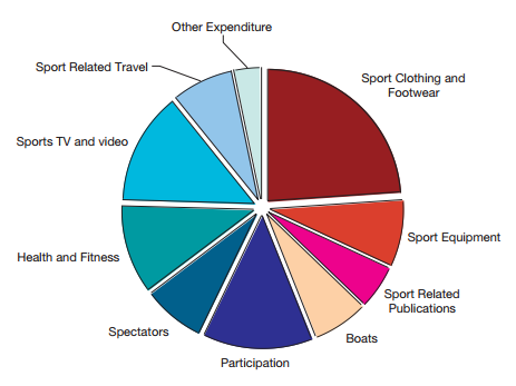
Figure 1. Breakdown of UK consumer spending on sport (Haake 2002).
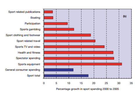
Figure 2. Growth in sport compared to the growth in general consumer spending. (Haake 2002).
2.2 Football Design
Increased televising of football has led to increased scrutiny of a football’s performance and the amount that they deviate during flight, particularly during World Cups (Haake 2002). This assignment focusses on the application of CAD/CAM technologies in the development of footballs.
Table 1 details some of the CAD/CAM tools and technologies that exist. Some of these have the potential to applied to football design and devlopment.
|
Technology |
CAD / CAM |
|
2D / 3D Modelling |
CAD |
|
Assembly / Constraints |
CAD |
|
Rendering |
CAD |
|
Finite Element Analysis (FEA) |
CAD |
|
3D Scanning |
CAD |
|
Computer Fluid Dynamics (CFD) |
CAD |
|
Additive Manufacturing /Rapid prototyping (3D Printing)
|
CAM |
|
CNC Machining
|
CAM |
Table 1. CAD/CAM Tools & Technologies.
4.1 3D Modelling
CAD applies computer technology to produce detailed 3D models and / or 2D drawings of components. It is throughout the development life cycle applied from concept design to property analysis and defining manufacturing methods (CAD Software 2017, Computer Aided Design 2017).
In the sports and leisure industry, a products looks are as important as its function. The product’s aesthetics and success in the sporting arena are hoped to encourage secondary sales on the high street. Aesthetics are determined by designers and Marketing by creating lifelike models in CAD. These designs can be used to test consumer responsiveness to the product, or to select the most appealing product from a series of designs without the requirement for multiple sketches. In CAD, colours and backgrounds can be changed at the flick click of mouse (Adidas Group 2013).
In addition, CAD models lay the foundations for the application of a variety of other tools which include simulation, virtual prototyping, finite element analysis and many others. Building designs in CAD rather than on paper, enables a seamless integration with other technologies (Bosch 2011).
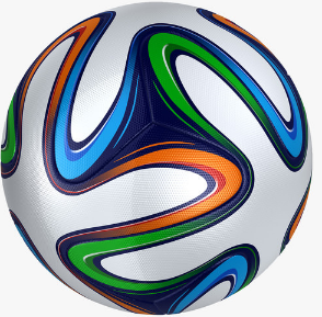
Figure 3. An Early 3D CAD Model of the Adidas Brazuca Football. (Adidas Group 2013).
4.2 Rendering
Rendering is the creation of an image from a CAD model. It creates product visualisations of the product in its environment which can be used throughout the design process, from communicating early concepts to obtain buy in, assessing customer interest in proposed products and helping to sell final products online or through marketing material before they physically exist. Such visualisations speed concept approvals, identify problems, sell products and can shorten time to market (A Picture’s Worth a Thousand Words 2014).
Josh Mings (Marketing Manager, Luxion) stated that “Designers and engineers have incredible opportunity to visualise their ideas. In the past, we were limited to whatever screenshots we could work up or, at best, arduously creating an exploded or cutaway view. Now, 3D rendering software allows us to create visuals that look as real as the end product communicating the idea before a piece of material is even cut.” (A Picture’s Worth a Thousand Words 2014).
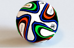
Figure 4. A 3D CAD Model of the Final Iteration of the Adidas Brazuca Football, Rendered onto a Crisp Background (Adidas Group 2013).
4.3 Finite Element Analysis (FEA)
Along with Computational Fluid Dynamics (CFD), FEA has been the most extensively applied technology to football design. FEA predicts a CAD model’s behaviour when subjected to a variety of conditions that may affect performance and determine if it will function to its design (Finite Element Analysis 2017). This is crucial to a product which would be under considerable media scrutiny during high profile events.
Yamagata University created a finite element model of a lower leg impacting a football. The velocity and spin of a football was studied for different impact location offsets from the centre of the ball. They found that spin increased as the ball was hit more to the side of the centre of mass. Reducing the coefficient of friction to zero did not reduce the spin to zero when the ball was hit off centre, as the ball’s deformation around the foot enabled torque to be applied. This allowed the foot to create spin even in wet weather (Arauju et al 2005). 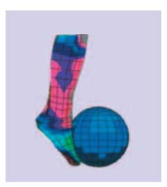
Figure 5. Finite element of the lower leg impacting a football (Haake 2002).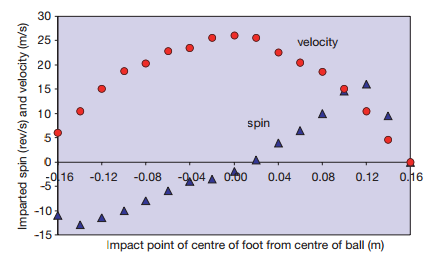
Figure 6. The effect of kicking position and friction and ball flight characteristics (Haake 2002).
A similar FEA was applied to the development of the Adidas Teamgeist ball for the 2006 World Cup and the Adidas Brazuca ball for the 2014 World Cup. In order to understand the effect of structural changes on the ball as a result of impact, the balls’ behaviour, when struck at 100mph, was modelled. This testing contributed to changes in the stiffness distribution of the carcass of the ball. (Cotton, Ross T., 2008).
“We needed repeatable, scientific results, the robot leg allowed us to kick a ball the same way every time. We can test the flight path, accuracy and speed. We can also wet the ball and test in different conditions too and even put different boots on the end of the leg to test how that affects everything.” (Adidas Brazuca World Cup Football Design 2014)
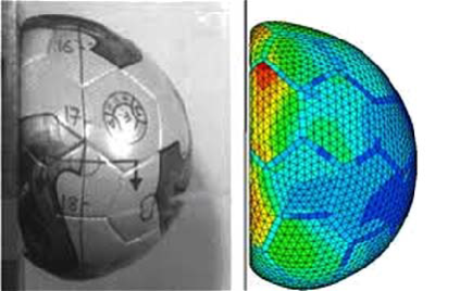
Figure 7. FEA structural testing of the Adidas Teamgeist (Cotton, Ross T., 2008).
4.4 Computational Fluid Dynamics (CFD)
CFD simulates fluid (either liquid or gas) passing through or around an object to predict the impact of such flows on product performance (CFD 2017).
Wind tunnel tests were performed by the University of Sheffield to assess the aerodynamics of footballs. The study showed that, as a football’s flight slows, it experiences a sudden jump in drag force of about 25%. The increased drag occurred at the end of the trajectory when the ball was travelling slowest and emphasised lateral deviations that occurred due to spin. Up until this experiment, lift and drag coefficients on spinning footballs had been difficult to gain. By applying CFD, it was found that the lift coefficient rose from zero for a non-spinning ball to about 0.2 for a ball with 100 rad/s of spin. (Arauju et al 2005).
This effect is known as ‘knuckling’. CFD showed that knuckling occurs in seamed balls where any slight movement makes the seam separation points alter position, leading to apparently random sideways deviations. (Haake 2002)
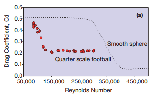
Figure 8. Drag coefficient vs Reynold’s number (Haake 2002).
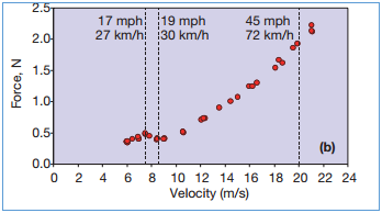
Figure 9. Measured drag forces on a quarter scale football vs Reynold’s number (Haake 2002).
A similar analysis was undertaken by Adidas to compare the behaviour of the Teamgeist and Jabulani balls, when developing the Teamgeist for the 2014 World Cup (NASA Turns World Cup into a Lesson in Aerodynamics 2015). The 2010 world cup football Jabulani was criticised for having an unpredictable trajectory “The 2010 World Cup ball, the Jabulani, was described as sometimes demonstrating supernatural movements. When kicked with little or no spin, the ball knuckled… Knuckling occurs when, at zero or near zero spin, the seams of the ball channel airflow in an unusual and erratic manner, making its trajectory unpredictable”. (NASA Turns World Cup into a Lesson in Aerodynamics 2014). Research was undertaken using CFD to determine the reasons for this. The Jabulani was compared to other Adidas footballs to develop a profile.
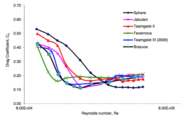
Figure 10. Drag Coefficient of various footballs(NASA Turns World Cup into a Lesson in Aerodynamics 2014).
The results indicated that the drag on the Jabulani ball varied with its panel orientation because the aerodynamic forces acting on the ball varied according to panel orientation making its movement unpredictable (NASA Turns World Cup into a Lesson in Aerodynamics 2014). “Knuckling occurs when, at zero or near zero spin, the seams of the ball, channel airflow in an unusual and erratic manner, making its trajectory unpredictable” Furthermore, the research showed that for the Jabulani, knuckling occurred at 55 mph, which is the average kicking speed of a professional footballer. The knuckling effect for a traditional ball is around 30 mph (Haake 2002), hence the Jubalini’s more frequent knuckling. To deliver a more predictable flightpath, for the Brazuca ball, the critical speed for maximum knuckling was designed to be around 30 mph. (NASA Turns World Cup into a Lesson in Aerodynamics 2014).
4.5 3D Scanning
3D scanning involves the laser scanning of components to enable their reproduction in 3D CAD (3D Laser Scan Parts 2017). Dr John Hart (Research Fellow, Sheffield Hallam University) laser scanned the surface of the Adidas Jabulani and Brazuca footballs to produce 3D CAD models of the balls’ seams (Secrets of the New World Cup Ball 2014). The seams on the Brazuca were shown to be deeper and longer than the Jabulani. The depth of the Jabulani’s seam was around 0.48 mm, whilst the Brazuca seam was measured at 1.56 mm deep. The length of the seams on the Jabulani was approximately 203cm whilst the Brazuca was around 327cm.
CFD tunnel tests confirmed that footballs with rougher surfaces (the Brazuca) travel further. As a football flies through the air, its seams stir and agitate the air with a similar effect of golf ball dimples. Dr Simon Choppin,
(Sheffield Hallam University) stated that “This agitation is essential for fast and reliable flight. The seams of a football disturb the flow of the air” (Secrets of the New World Cup Ball 2014).
The Brazuca had different seam geometry to that of the Jabulani which meant that the 2 balls’ trajectories differed during CFD analysis (Secrets of the New World Cup Ball 2014). As panel seams have been shown to impact up a football’s trajectory, this analysis would be important in determining its characteristics.
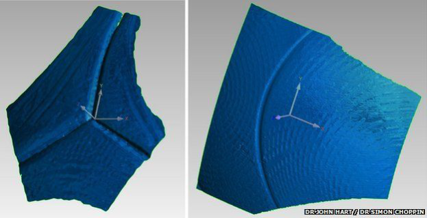
Figure 11. The Brazuca (left), has different seam geometry to that of the Jabulani ball (right). (Secrets of the New World Cup Ball 2014).
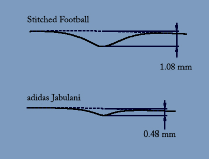
Figure 12. Comparison of the Adidas Jabulani and standard stitched football (Secrets of the New World Cup Ball 2014).
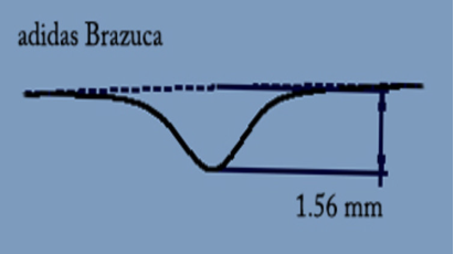
Figure 13. Seam profile of the Adidas Brazuca (Secrets of the New World Cup Ball 2014).
Sales of Replica World Cup Footballs are worth on average $500m to Adidas, sales of which peak during the tournament itself (Adidas Releases Soccer Ball Worth Half a Billion Dollars 2013). This is exemplifies the commercial value that a football can represent to a manufacturer. To maximise commercial gains, it is imperative that the product is brought to market on time, be aesthetically appealing and perform as expected, in this example, during the tournament. Concept approval by customers, simulation, testing and redesign must be completed satisfactorily, in a timely manner, to ensure that sales are maximised. Product development costs must also be minimised to maximise profit.
CAD supports this by driving lower product development costs, increasing productivity, improving quality and speeding time to market (CAD 2017) enabling an organisation to remain competitive or gain an advantage.
In addition, CAD provides:
- Improved visualisation of the final product, sub-assemblies and constituent parts speeding the design process.
- Greater accuracy, reducing iterations and defects.
- Simple, robust design documentation.
- Simple replication of design data and best practice (CAD 2017).
|
Technology |
Cost of Technology* |
Cost of Employee** |
Return on Investment |
|
CAD Modelling |
£3,000 |
£13,333 |
Designs can be used to test consumer responsiveness to the product. Feeds other CAD technologies. |
|
CAD Rendering |
£3,000 |
£13,333 |
Faster concept approval, problem identification and time to market |
|
FEA |
£25,000 |
£13,333 |
Predicts a CAD model’s behaviour when subjected to a variety of conditions. Issues can be resolved prior to manufacture. |
|
CFD |
£25,000 |
£13,333 |
Simulates the impact of gas/liquid flows on product performance. Issues can be resolved prior to manufacture. |
|
3D Laser |
£25,000 |
£13,333 |
Enables reproduction of existing products to be fed into CADCAM technologies for analysis. |
Table 2. Return on Investment Analysis
* Ascertained through obtaining average quotes form internet sources
**Hypothetical 3 month period @ £40,000 p.a.
The cost estimates in table total £147,665. When set against the headline sales figure of $500m for the sale of world cup footballs, assuming that profit makes up a significant part of this figure, it suggests that the ROI is significant due to the advantages discussed previously. In addition, if competitors such as Nike, are kept out of the market and denied profit as a result, there is a double payback.
Although the development costs are unknown, it would appear that, to remain competitive in a high profile market such as football, CAD is a must in supporting development
6.1 3D Image
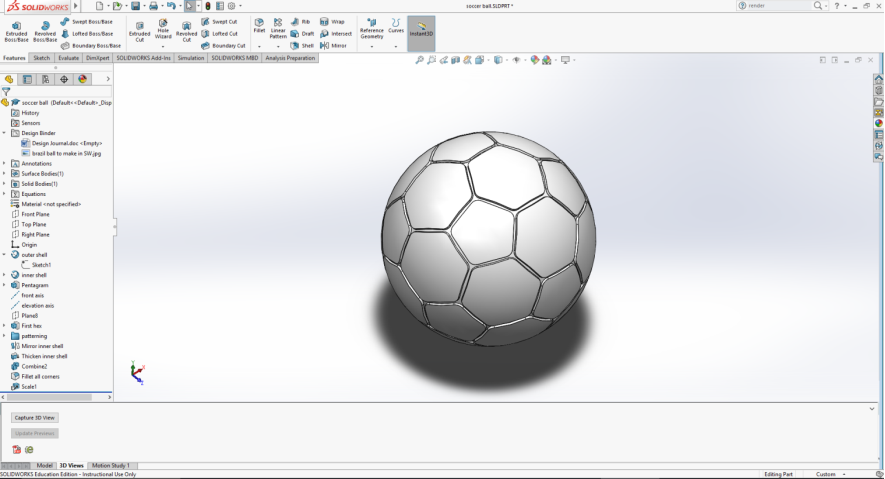
Figure 14. 3D CAD Model, Designed in SolidWorks.
6.2 Rendered Image – Urban Setting
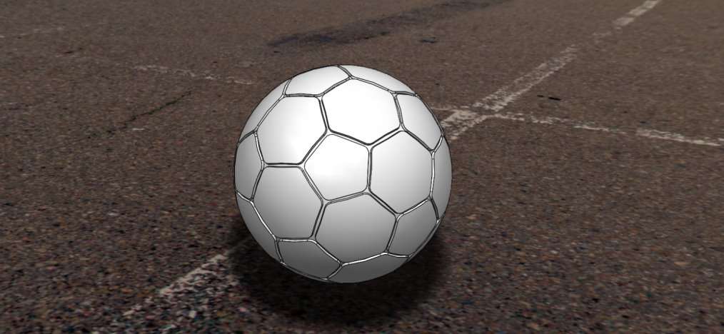
Figure 15. 3D CAD Urban Rendering, Designed in SolidWorks.
6.3 Rendered Image – Playing Field Setting
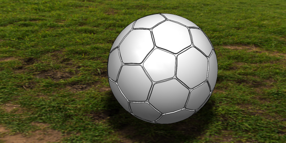
Figure 16. 3D CAD Playing Field Rendering, Designed in SolidWorks.
6.4 CAD Model and Rendering Discussion
As the author had no CAD experience prior to the Module, a simple model was created and rendered in two different environments to demonstrate how the same product could be advertised in different ways to appeal to different customers, the urban footballer and footballer’s who have access to playing fields. This demonstrates the versatility of CAD and supports the ROI section in that 2 different scenarios can be presented at the click of a button for internal approval, customer comment and advertising.
3D Laser Scan Parts [Online]. http://www.jensen-consulting.co.uk/cad-drafting-services/reverse-engineering/3d-laser-scan-parts [Accessed: 21st March 2017].
A Picture’s Worth a Thousand Words [Online]. http://www.3dcadworld.com/pictures-worth-thousand-words-rendering-increasingly-important-product-development/ [Accessed: 21st March 2017].
Adidas Brazuca World Cup Football Design [Online]. https://www.dezeen.com/2014/07/13/adidas-brazuca-world-cup-2014-football-design/ [Accessed: 21st March 2017].
Adidas Group [Online]. www.adidas-group.com/media/filer_public/2013/07/31/gb_2012_en.pdf [Accessed: 26th March 2017].
Adidas Releases Soccer Ball Worth Half a Billion Dollars [Online]. http://keepingscore.blogs.time.com/2013/12/03/adidas-releases-soccer-ball-worth-a-half-billion-dollars/ [Accessed: 26th March 2017].
Araujo, D., Cabri, J. and Reilly, T. (2005). Science and Football V. London: Routledge, Taylor & Francis Group, pp. 26-37.
Bosch, G., (2011). [Online]. Create Better, Safer Designs by Interfacing CAD Models with Algor Analysis Capabilities. http://www.algor.com/news_pub/user_reviews/1999/bosch/bosch.asp [Accessed: 26th March 2017].
CAD Software [Online]. www.autodesk.com/solutions/cad-software [Accessed: 21st March 2017].
CFD [Online]. https://www.plm.automation.siemens.com/en_gb/plm/cad.shtml [Accessed: 21st March 2017].
CFD [Online]. http://www.solidworks.co.uk/sw/products/simulation/computational-fluid-dynamics.htm [Accessed: 21st March 2017].
Computer Aided Design [Online]. https://en.wikipedia.org/wiki/Computer-aided_design [Accessed: 21st March 2017].
Cotton, Ross T., (2008). [Online]. Surface Interactions of Soccer Balls https://dspace.lboro.ac.uk/2134/10765 [Accessed: 21st March 2017].
Finite Element Analysis [Online]. http://www.autodesk.com/solutions/finite-element-analysis [Accessed: 21st March 2017].
Haake, S., (2002). Sports Engineering. Injenia Magazine, 12 (2), p. 24 -30.
Mehta, R., (2014). [Online]. NASA Turns World Cup into a Lesson in Aerodynamics. https://www.nasa.gov/content/nasa-turns-world-cup-into-lesson-in-aerodynamics [Accessed: 18th March 2017].
What is Sports Engineering? [Online]. http://www.sportsengineering.org/students/what-is-sports-engineering/ [Accessed: 18th March 2017].
Reflection
Prior the Puzzle Project, the author had no experience of CAD/CAM and had never seen it in use. Experience within the team was very limited, so it was important that the team dynamic was such that everyone contributed to the best of their ability.
The team worked well together. One member of the team did have a very small amount of CAD experience but it was important that the expectation of the team was not too high. This is why it was agreed that the design should be simple, so that it would be achievable given the available skill set.
The team opted to use the London Underground sign as the basis for a puzzle. Determining how something that was traditionally in one piece could be broken down into constituent parts, to form a puzzle, was challenging. Although the focus of the course was on technology, traditional pencil and paper sketches proved invaluable in generating the initial concepts.
Generating the agreed concept in SolidWorks proved to be difficult given that all the experience, albeit limited, lay with one member of the team. The other members of the team were supportive and helped where possible, however, the onus was very much on that individual. The author was on the periphery of the CAD modelling process. However, watching the model develop, turn, be separated and joined together on screen was impressive and provided the author with an interest in the process and a desire to learn more. For the first time on the degree programme, the author found the practical work to be stimulating, thought provoking and interesting. Applications outside of the automotive industry were apparent. Thoughts were also taken into the Post Module Assignment (PMA), where the author was excited to understand that CAD could be applied to the manufacture of anything, including things of interest to them, the basis of the PMA would therefore be formed by a subject outside of the traditional realms of engineering.
The concept of rendering was introduced during the CAD stages of the project. Again, this was new to the author and would prove beneficial in supporting the PMA.
Watching the tool path being developed in Alpha Cam was very impressive and again, stimulating. Simulation highlighted issues with engraving lettering onto the design. The simulation was run with a 1mm bit but the text was not clear. The lettering was adjusted to be engraved more deeply which improved the aesthetics but raised a concern around longevity of the drill bit and the impact on price per unit.
Find Out How UKEssays.com Can Help You!
Our academic experts are ready and waiting to assist with any writing project you may have. From simple essay plans, through to full dissertations, you can guarantee we have a service perfectly matched to your needs.
View our academic writing services
Prior to the module, the author understood that components and products could be designed in CAD but how this happened was not clear. The module filled this learning gap. The author was also unaware of CAM, what it was or what it did. The simulation tools and the interaction with CNC, 3D printing etc were particularly new concepts to the author and they found them to be interesting and knowledge enhancing.
If the author were to perform the task again, they would spend some time working with CAD/CAM technology in advance so that they could add more value to the process. Research into different methods of applying lettering to designs would also be given so that a more robust solution could be implemented.
It is rare that the author has completed a module and felt like they have learned something that they will remember or has given them a greater understanding of how modern manufacturing works form CAD to CAM and the other technologies in between. Although the author is by no means a CAD/CAM expert, they now feel that they can talk about the subject with confidence.
Cite This Work
To export a reference to this article please select a referencing style below:


