Concrete Mix Design Using DoE Method
[Author]
Click or tap here to enter text.
Click or tap here to enter text.
Click or tap here to enter text.
Contents Page
1. Introduction
1.1. In this report I will calculate the exact amount of materials required to produce 1m3 of concrete, designed to the Department of Environment (DoE) method. This method of concrete design was first introduced in 1950, under the name “Road Note No 4”, which was later replaced by “Design of Normal Concrete Mixes” in 1975 by the British Department of Environment (DoE). The design guidance was updated in 1988 to account for changes in the then current British Standards and is still used today, often being referred to as the British Standard concrete mix design.
1.2. The DoE method for concrete mix design works by calculating the values of 8 fundamental processes:
- Mean target compressive strength
- Water/Cement ratio
- Water content using required slump value and aggregate size
- Cement content
- Concrete density
- Aggregate content
- Proportion of fine & course aggregate
- Course aggregate
2. Design Requirements and Assumptions
2.1. Below is a list of design requirements/assumptions that have been used for the concrete mix design:
- A slump of 10mm to 30mm.
- A characteristic 28-day compressive strength of 30 N/mm2 (5% failures permitted).
- The standard deviation of the tests is σ = 6.1 N/mm2.
- Ordinary Portland cement (42.5 N).
- Crushed sand of 2.7 density and 60% passing through a 600 µm sieve.
- Crushed coarse aggregate 2.6 density and 20mm are used.
3. Mean Compressive Strength
3.1. The target mean compressive strength
can be calculated by:
Table 1. Risk factor values used in statistical control (G.D.Taylor, 2000)
|
Percentage failure permitted |
Risk factor value |
|
16 |
1.00 |
|
10 |
1.28 |
|
5 |
1.64 |
|
2.5 |
1.96 |
|
2 |
2.05 |
|
1 |
2.33 |
4. Water / Cement Ratio
4.1. The water / cement ratio is determined by using data from table 2.
Table 2. Approximate compressive strength of concrete made with a free Water/Cement ratio of 0.50 (G.D.Taylor, 2000)
|
Type of cement |
Type of coarse aggregate |
Compressive Strength (N/mm2) |
|||
|
Age (days) |
|||||
|
3 |
7 |
28 |
91 |
||
|
Ordinary Portland Cement (OPC) Or Sulphate-resisting Portland (SRPC) |
Uncrushed |
22 |
30 |
42 |
49 |
|
Crushed |
27 |
36 |
49 |
56 |
|
|
Rapid-hardening Portland (RHPC) |
Uncrushed |
29 |
37 |
48 |
54 |
|
Crushed |
34 |
43 |
55 |
61 |
|
|
1 N/mm2 = 1 MN/m2 = 1 MPa |
|||||
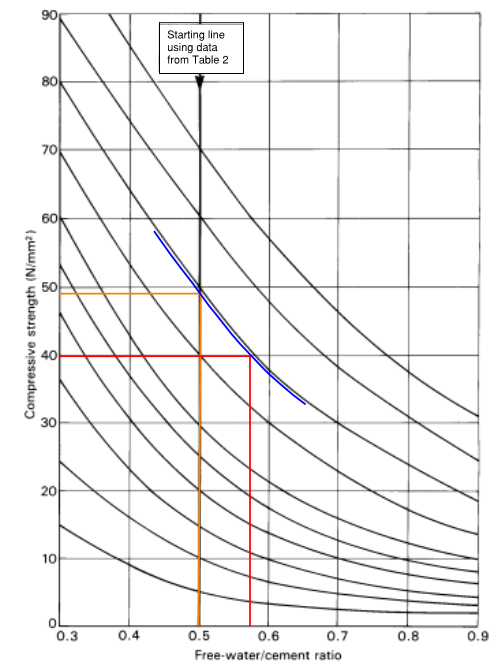
4.2. One of the requirements of the design mix stated that the mix will use ordinary Portland cement, with crushed aggregate, therefore, the 28-day strength value of 49 N/mm2 from the above table can be used to calculate the water / cement ratio:
- 0.5 is used for the free-water/cement axis as this value is used in table 2.
- At the point of intersection of compressive strength value of 49 N/mm2 with the free-water / cement value 0.5 (orange), the nearest curve is offset parallel to the point of intersection (blue).
- A horizontal line is drawn starting at the desired compressive strength of 40 N/mm2, until it intersects with the parallel curve, with a vertical line drawn from this point of intersection to find the desired free-water / cement ratio of 0.57 (red).

Figure 1. Desired free-water / cement ratio (G.D.Taylor, 2000)
5. Water Content
5.1. To calculate the required water content to achieve a suitable concrete workability, the following factors are used:
- Slump value (10 mm – 30 mm)
- Aggregate size (20 mm)
The values of these factors have been provided in the design requirements and can be found in table 3.
5.2. Using the information provided in Table 3 (below), we can determine that the required water content is 190 kg/m3by intersecting the value at 20 mm aggregate size and 10 mm – 30 mm slump value for crushed aggregate.
Table 3: Workability and approximate free-water content (G.D.Taylor, 2000)
|
Slump (mm)
Vebe (seconds) |
Very Low 0 – 10 >12 |
Low 10 – 30 6 – 12 |
Medium 30 – 60 3 – 6 |
High 60 – 180 0 – 3 |
|
|
|||||
|
Maximum size of aggregate (mm) |
Type of aggregate |
Water content (kg/m3) |
|||
|
10 |
Uncrushed Crushed |
150 180 |
280 205 |
205 230 |
225 250 |
|
20 |
Uncrushed Crushed |
135 170 |
160 190 |
180 210 |
195 225 |
|
40 |
Uncrushed Crushed |
115 155 |
140 175 |
160 190 |
175 205 |
|
|||||
|
Percentage of fly ash in cementitious material |
Reduction in water content (kg/m3) |
||||
|
10 |
5 |
5 |
5 |
10 |
|
|
20 |
10 |
10 |
10 |
15 |
|
|
30 |
15 |
15 |
20 |
20 |
|
|
40 |
20 |
20 |
25 |
25 |
|
|
50 |
25 |
25 |
30 |
30 |
|
6. Cement Content
6.1. To calculate the amount of cement required, the following formula is used
The values for both water content and free-water / cement ratio are known, so it is easily calculated.
7. Density of Concrete
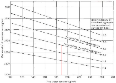
7.1. The DoE method uses a graphical system for calculating the density of the fresh concrete, using the relative aggregate density and free-water content.
7.2. The relative aggregate density has been provided at 2.6, and the free-water content is 190 kg/m3, therefore the density can be calculated to be 2370 kg/m3, as shown in figure 2.

Figure 2. Fresh Concrete Density (G.D.Taylor, 2000)
8. Aggregate Content
8.1. Using the fresh concrete density of 2370 kg/m3, and the aggregate content can be calculated using the following formula:
These values have already been calculated, therefore:
9. Fine aggregate content
9.1. The proportion of fine aggregate in the concrete mix will depend on:
- The grading of the sand
- Maximum aggregate size
- Workability of the concrete
- Free-water / cement ratio
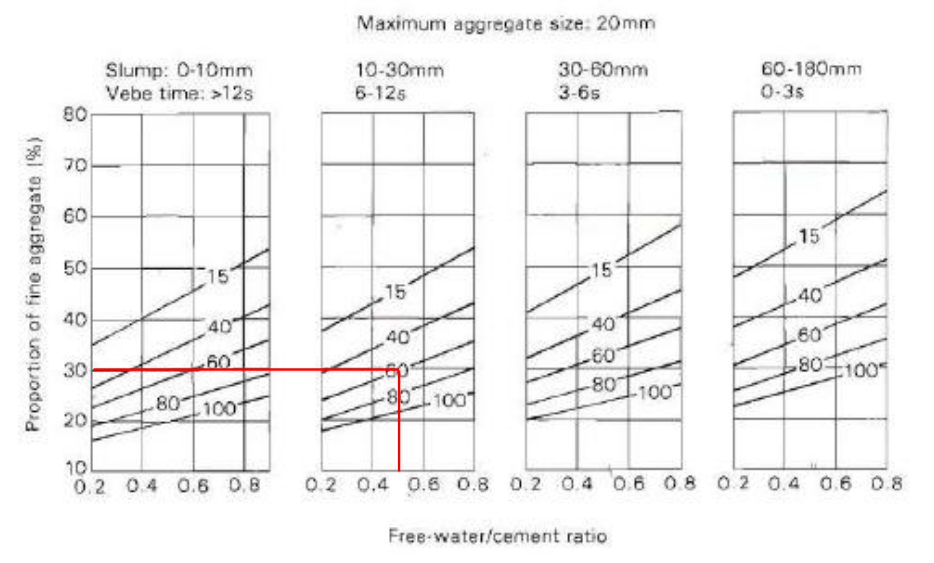
9.2. Figure 3 (below) shows the graphical method of calculating the proportion of fine aggregate, which gives a result of 30% by starting at 0.5 free-water/cement ratio and drawing a line vertically upwards to the percentage of fine aggregate passing through a 600 µm sieve (60%). A horizontal line is then drawn to find the proportion of fine aggregate.

Figure 3. Recommended proportions of sand according to percentage passing a 600 µm sieve (G.D.Taylor, 2000)
Using the total aggregate content 1847 kg/m3, the proportion of fine aggregate can be calculated.
10. Coarse Aggregate Content
10.1. Once the fine aggregate content has been calculated, we can simply deduct this value from the total aggregate content to determine the amount of coarse aggregate required.
11. Summary
11.1. From the calculations above, it can be determined that for each m3 of concrete, the correct amounts for each component are as follows:
Table 4. Quantity of materials required to produce 1m3 of concrete with a 28-day compressive strength of 30 N/mm2, designed to the DoE method.
|
Material |
Quantity (kg/m3) |
|
Cement |
333 |
|
Water |
190 |
|
Fine Aggregate |
554 |
|
Coarse Aggregate |
1293 |
References
- G.D.Taylor, 2000. Materials in Construction – An Introduction. 3rd ed. Essex: Pearson Education Limited.
Cite This Work
To export a reference to this article please select a referencing style below:


