SUBSURFACE LAYER CHARACTERISATION FOR ENGINEERING PURPOSES USING VERTICAL ELECTRICAL SOUNDING IN BANANA ISLAND, LAGOS, NIGERIA
OLADUNJOYE, H.T., 2OLALEYE, A.O.
ABSTRACT
Seven (7) vertical electrical sounding stations along two traverses were used to study the depth to competent formation for foundation of engineering structures in Banana Island of Lagos. The study is meant to unravel the presence of problem soils that can be inimical to structures.
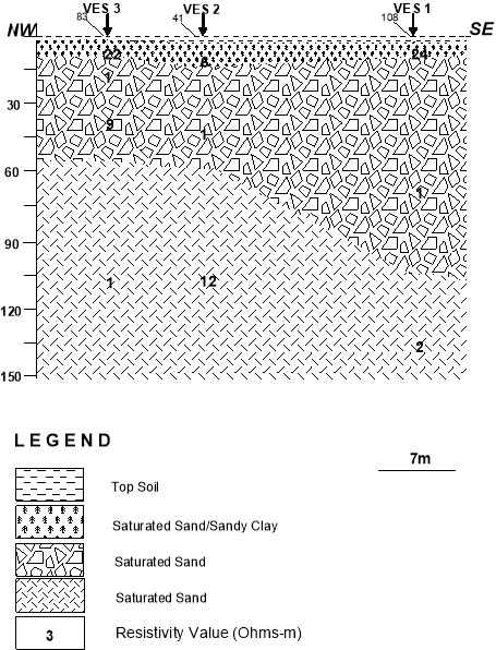
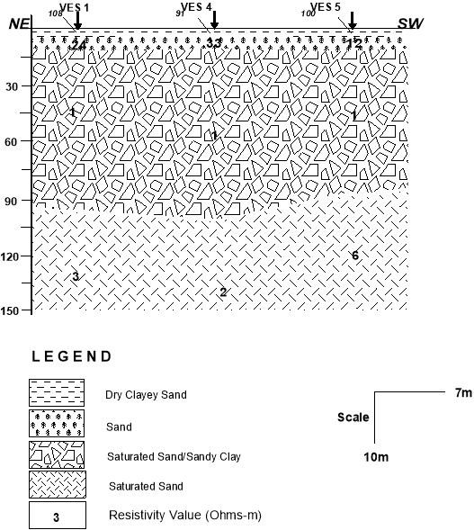
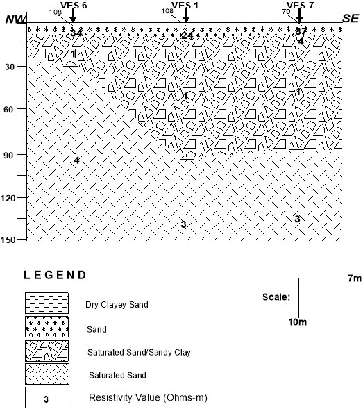
The sounding data used in this study was acquired using Schlumberger Electrode Configuration. The VES data were interpreted into a model curve using forward modelling software called Winglink. The interpretation parameters (layer resistivities and thicknesses) for each VES point were grouped into three geo-electric sections to represent the 2-D models of the subsurface layers in the study area.
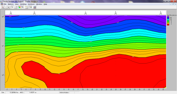
The final interpretation results (resistivities and depths) modelled as geoelectrical sections and pseudosections were compared within the surveyed area and correlated with the borehole log-derived depths to determine a probable depth for foundations of high rise building.
The study concluded that the geophysical investigation is of great significance in partial curve matching interpretation technique gives the most consistently low percentage deviation error margins amongst the three VES preliminary interpretation techniques. There is consistent increase in depth prediction error, with depth, in all the interpretation techniques.
INTRODUCTION
Geophysical resistivity techniques are based on the response of the earth to the flow of electrical current. In all methods, an electrical current is passed through the ground and the resulting potential electrodes allow us to record the resultant potential difference between the current electrode is measured. The apparent resistivity is then a function of the measured impedance (ratio of potential to current) and the geometry of the electrode array. Depending upon the survey geometry, the apparent resistivity data are plotted as 1-D soundings, 1-D profiles, or in 2- D cross-sections in order to look for anomalous regions.
Get Help With Your Essay
If you need assistance with writing your essay, our professional essay writing service is here to help!
In the shallow subsurface, the presence of water controls much of the conductivity variation. Measurement of resistivity (inverse of conductivity) is, in general, a measure of water saturation and connectivity of pore space. This is because water has a low resistivity and electric current will follow the path of least resistance. Increasing saturation, increasing salinity of the underground water, increasing porosity of rock (water-filled voids) and increasing number of fractures (water-filled) all tend to decrease measured resistivity.
Resistivity measurements are associated with varying depths depending on the separation of the current and potential electrodes in the survey, and can be interpreted in terms of a lithologic and/or geohydrologic model of the subsurface. The choice for Direct Current (DC) resistivity survey in this project is as a result of its ability to provide a quick synoptic picture of lithological and groundwater characteristics in terms of its apparent resistivity contrast. In this work the electrical resistivity character collected were model with Winresist and Winglink inversion software. The layers parameters (resistivities and thicknesses) obtained from data processing were then inverted with Winglink to provide two-dimensional images of the subsurface apparent resistivity variation (Pseudosection). However, knowledge on the geology of the area from acquired borehole log has played a vital role in determining the best fit model.
MATERIALS AND METHOD OF STUDY
The vertical electrical resistivity is used to determine the subsurface resistivity distribution and depth of the sub-surface layers with the aid of electrical resistivity meter. In this study, Schlumberger array of electrical resistivity method was adopted because of the low cost of the field operation, reduced logistics man power and also faster. A total of Six (6) vertical electrical sounding (VES) were measured within the area.
The resistivity measurement is taken by introducing small portion of electricity through two current electrodes (A and B) and measuring the resultant voltage drop between a pair of potential electrodes (M and N). A simple calculated value of apparent resistivity  is the parameter bearing the information for the characteristics of the subsoil (Tonkov, 2008).
From the foundation of electrical resistivity theory is the ohm’s law (Grant and West, 1965; Dobrin and Sarvit, 1988):
 (1)
(1)
Where ρ is the resistivity, R is the resistance, L is the length of the conducting cylinder and A is the cross sectional area.
For the solid earth, whose material is predominantly made up of silicates and basically non conductors, the presence of water in the pore space of the soil and in the rocks fractures enhances the conductivity of the earth when an electrical current I is passed through it, thus making the rocks a semi conductor. Since the earth is not like a straight wire and it is not an anisotropic, then Equation 1 can be customized as:
 (2)
(2)
Where  change in voltage and r is is the radius of current electrodes’ hemisphere. Since the earth is not homogeneous, Equation 2 is used to define an apparent resistivity
  which is computed as the product of the geometric factor and the resistance recorded in the electrical resistivity meter and resistivity the earth would have if it were homogeneous (Grant and West, 1965;):
 (3)
(3)
Where, 2πr is then define as the geometric factor (G) fixed for a given electrode configuration and is dependent on the electrode arrangement.
The Schlumberger electrode configuration was used for this study. The geometric factor is thus given as:
 (4)
(4)
Where AB is the distance between two current electrodes, MN is the distance between two potential electrodes.
LOCATION AND GEOLOGY OF THE STUDY AREA
The study area is located in the south-eastern part of Lagos State between Latitudes 6° 25′ to 6° 28′ North of the Equator and Longitudes 3° 24′ to 3° 30′ East of the Greenwich Meridian (Fig.1.1). The study area Lekki and it’s environ issituated within the western Nigeria coastal creeks and lagoon developed by barrier beaches associated with sand deposition (Pugh, 1954). It forms part of the Lagos lagoon system known as the largest of the four lagoon system in the gulf of guinea coast (Adepelumi and Olorunfemi, 2000).
Banana Island is an artificial island in Lagos State, Nigeria. It is located in the Lagos Lagoon and attached to the North-Eastern Ikoyi Island by a dedicated road strip which is linked to the existing road network. The banana-shaped Island is approximately 1,630,000 square metres in size (less than a square mile) and is divided into 536 plots (of between 1000 and 4000 square metres in size) mainly arranged along cul-de-sacs, so designed to enhance the historically residential nature of Ikoyi.
Banana Island is an artificial island reclaimed from portions of the Lagos Lagoon, topographic elevation obtained at the site averaged 4 metres above mean sea level. The study area is located within the coastal region of Nigeria with a climate of long wet season (April to October) and short dry season (November to March). Average annual precipitation is above 2000mm and serves as a source of groundwater recharge. The area is susceptible to flooding after heavy rainfall during the wet season.
Nigeria lies in an extensive Pan-African mobile belt which separates the West African and Congo Cratons. The belt is interpreted to have evolved from the continental collision between the West African craton and the Pan-African belt (Black et al., 1979; Caby et al., 1981). Geochronologically, the Precambrian rocks of Nigeria can be grouped into four major classes (Liberian Orogeny 2800 ± 200 Ma, Eburnean Orogeny 2000 ± 200 Ma, Kibaran Orogeny 1100 ± 200 Ma and The Pan-African Orogeny 600 ± 150 Ma). These classes correspond with the four orogenic events that have punctuated the Precambrian history of Africa (Odeyemi, 1979).


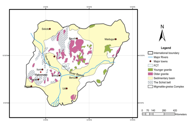
Figure 2.1: Regional Geological Map of Nigeria (Modified after Ajibade et al., 1988)
Coastal Nigeria comprises two sedimentary basins: The Benin-Dahomey basin and the Niger Delta basin separated by the Okitipupa ridge. The rocks of the Benin basin are mainly sands and shales with some limestone which thicken towards the west and the coast as well as down dips to the coast. Recent sediments are underlain by the Coastal Plains Sands which is then underlain by a thick clay layer – the Ilaro Formation and other older Formations (Jones and Hockey, 1964).
The Coastal Plains Sands aquifer is a multi-aquifer system consisting of three aquifer horizons separated by silty or clayey layers (Longe et al., 1987). It is the main aquifer in Lagos Metropolis that is exploited through boreholes for domestic and industrial water supply.
The sedimentary rocks of Lagos State are composed of five (5) sedimentary formations (Jones and Hockey, 1964) viz: Abeokuta Formation, Ewekoro Formation, Ilaro Formation, the Coastal Plains Sands and the alluvial deposits. The coastal plains sand also known as the Benin Formation stretches across the Dahomey basin into the Niger Delta Basin.
The geological formations of the study area composed of sediments laid down under fluviate, lascustrine and marine environments. These sediments grade into one another and vary widely in lateral extent and thickness (Adepelumi and Olorunfemi 2000). Longe et al., (1987) classified the aquifer into three types.
Quantitative interpretation of the curves involved partial curve matching using two-layer Schlumberger master curves and the auxiliary K, Q, A and H curves.
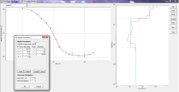
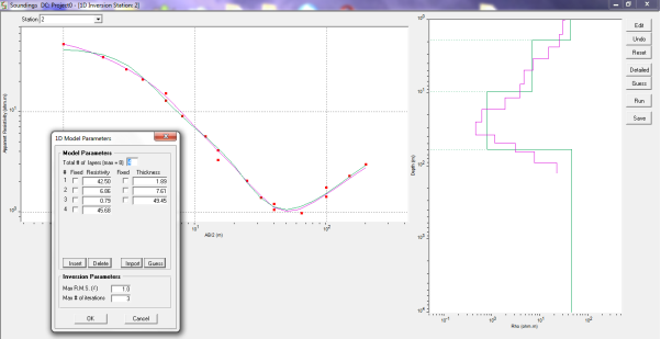
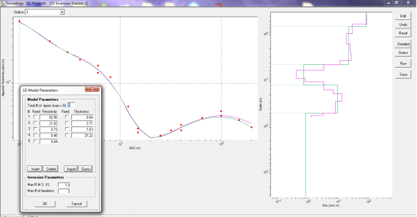
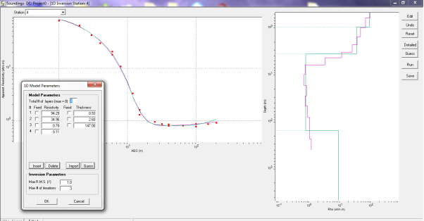
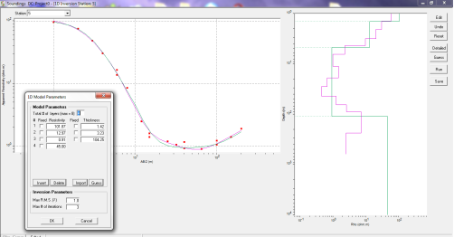
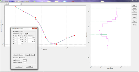
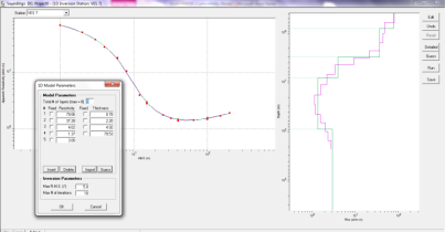
Output from the quantitative interpretation was modelled using computer iteration. The Resist Version 1.0 interpretation software was used for iteration and presentation of the curves (see Figures 3a – f).
RESULTS AND DISCUSSIONS
The apparent resistivities from the field plotted on a log-log graph survey against the corresponding half Schlumberger electrode spacing was interpreted using the computer iteration technique. The initial model was deriving by winresist software by entering layer parameters from partial curve process as the starting parameters. The resulting models were then iterated till the best fit curve as attained.
In all, there was a large value for root mean square (r.m.s) error resulting mostly from the scattered point data observed where half Schlumberger electrode spacing  is greater than 32m.
In order to view the resistivity distribution of the whole surveyed area, the result of the soundings data linearly and vertically interpolated into two dimensional pseudosections.
The borehole records from the geo-technical investigation were used as a control in interpreting the VES data acquired in this study. Interpretation of the geo-electric curves was essentially based on the fact that resistive materials constitutes zones of interest for engineering construction, considering that clay and organic materials are conductive and typified by low resistivity values(reference).
The outputs from the manual interpretation were modelled using computer iterations. Resist Version 1.0 software was utilized for the iterations. The curve types obtained are 3 – layer H (VES 1), 4 – layer QH (VES 2, VES 3 and VES 6) and 5 – layer QHK (VES 4 and VES 5), as shown in Figures 3a – f.
VES 1 and VES 6 with RMS-error (Root Mean Square) of 11.7 and 10.4 respectively present better quality data than VES 2 to VES 5 with RMS-error ranging from 12.7 to 20.8, thus the interpretation of the geo-electric curves at VES 1 and VES 6, present more reliable results.
From the iteration of VES 1, depth to competent bedrock (sand) is 39.6 metres, while depth to competent (sand) layer at VES 6 is 39.8 metres, this is signified by the rising segment of the curve at both VES stations, typified by a relatively resistive material (5 – 105 Ω-m).
CONCLUSION
This paper describes the possibility of locating a competent formation for high rise building in area around Banana Island Ikoyi using Schlumberger array. The results of the interpretation of field survey reveal only the presence such formation in depth close to 10m. At this depth saturated sandy clay can be obtain virtually for all the VES stations. This saturated sandy clay formation provides good foundation support for any high rise due to the fact that the liquefaction potential is very low compare to all other formation inferred from geologic section.
REFERENCE
Alile, M.O., S.I. Jegede and O.M. Ehigiator, 2008. Underground water exploration using electrical resistivity method in Edo State, Nigeria. Asian J. Earth Sci., 1: 38-42.
Anderson, N. L. Selection of Appropriate Geophysical Techniques: A Generalized Protocol
Based on Engineering Objectives and Site Characteristics. Proc., 2006 Highway Geophysics-
NDE Conference, 2006, pp. 29-47. Available at http://2006geophysics.mst.edu/.
Anderson, N. L., A. M. Ismail, and T. Thitimakorn. Ground-Penetrating Radar: A Tool for
Monitoring Bridge Scour. Environmental and Engineering Geoscience, Vol. 13, 2007, pp. 1-10.
Dobrin, M.B. and C.H. Savit, 1988. Introduction to Geophysical Prospecting. 4th Edn., McGraw Hill Book Co., New York.
Dogara, M.D., B.M. Dewu and C.O. Ajayi, 1998. Groundwater potential of Romi, Kaduna. Nig. J. Physics., 10: 85-90.
Grant, F.S. and G.F., West, 1965. Interpretation Theory in Applied Geophysics. McGraw-Hill, New York.
Nwankwo L.I., P.I. Olasehinde and E.B. Babatunde, 2004. The use of electrical resistivity pseudo-section in elucidating the geology of an east-west profile in the basement complex terrain of Ilorin, West-Central Nigeria. Nig. J. Pure Applied Sci., 19: 1672-1682.
Olasehinde, P.I., 1999. An integrated geological and geophysical exploration for groundwater in the basement complex of west central Nigeria. Water Resourses, 10: 46-49.
Olasehinde, P.I., A.E. Annor and P.C. Pal, 1986. A geological evaluation of a prospective site for a weir on river Oyun, Ilorin, Nigeria. 7. Angew Geowiss, 8: 83-90.
Olorunfemi, M.O and S.A. Fasoyi, 1993. Aquifer types and the geoelectric/hydrogeologic characteristics of part of the central basement terrain of Nigeria (Niger State). J. Afr. Earths Sci., 16: 309-317.
Plummer, C.C., D. McGeory and D.H. Carlson, 1999. Physical Geology. 8th Edn., McGraw Hill Co. Inc., New York, pp: 48-56.
Rabiu, A.B, I. A. Adimula, K. Yumoto, J. O. Adeniyi and G. Maeda, 2009. Preliminary results from the magnetic field measurements using MAGDAS at Ilorin, Nigeria. Earth Moon Planets, 104: 173-179.
Rahaman, M.A., 1973. Review of the Basement Geology of South Western Nigeria. In: Geology of Nigeria, Kobe, C.A. (Ed.). 2 Edn., Rockview Publishers, Jos, Nigeria.
Singh, K.K.K., A.K.S. Singh, K.B. Singh and A. Sinha, 2006. 2D resistivity imaging survey for siting water-supply tube wells in metamorphic terrains: A case study of CMRI campus, Dhanbad, India. The Leading Edge, 25: 1458-1460
Cite This Work
To export a reference to this article please select a referencing style below:


